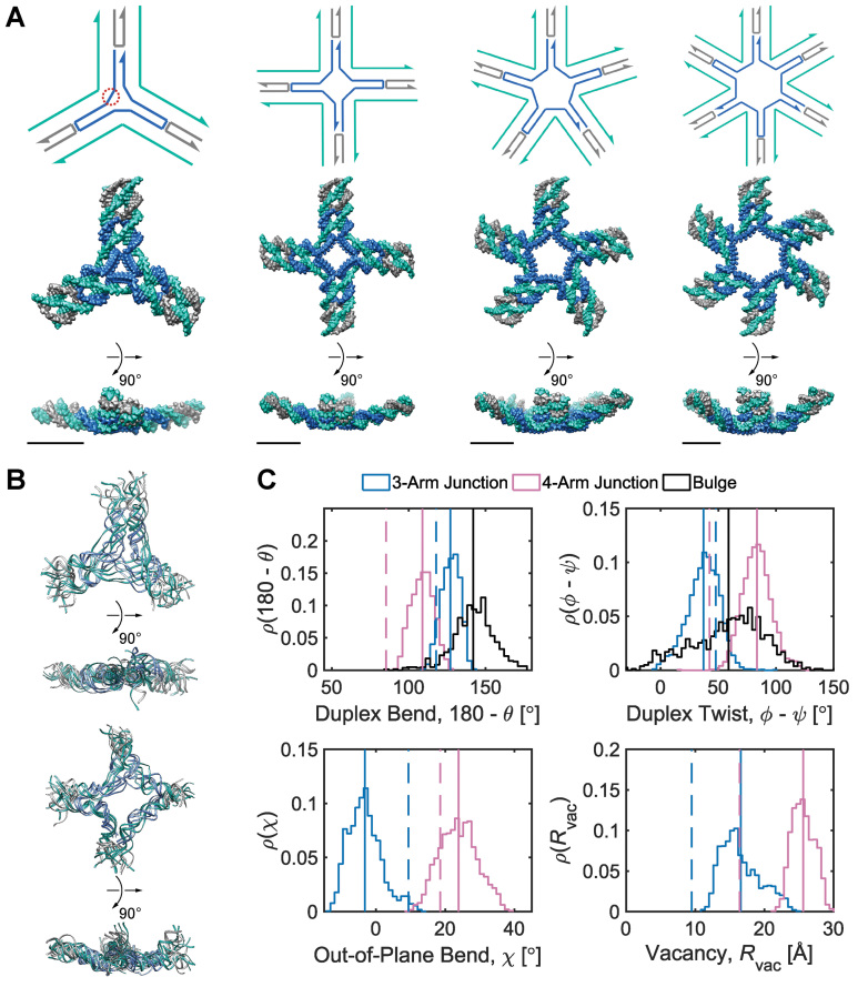
Figure 2.
Mechanical models of unconstrained multi-arm vertices. (A) Secondary structures (top) and corresponding FE models at the ground-state mechanical free energy (bottom) of 3-arm, 4-arm, 5-arm, and 6-arm vertices consisting of duplexes, double crossovers, single crossovers, and bulges. An N-arm vertex contains N ssDNA regions, each of which comprises five unpaired thymine bases. As an example, one of the three ssDNA regions in the 3-way vertex is encircled by red dots. The secondary structure and the first orthogonal view of each vertex are oriented such that the minor grooves of DNA at the center of the vertex face the reader. The FE models are represented as all-atom models with DNA stranded colored in the same way as in the secondary structures. All scale bars are 5 nm. (B) (Top) Four aligned snapshot sampled at 100, 200, 300, and 400 ns in the MD trajectory of the 3-arm junction. (Bottom) Four aligned snapshot sampled at 100, 200, 300, and 400 ns in the MD trajectory of the 4-arm junction. (C) Histogram of various geometric values calculated from MD trajectories. Duplex bend-angles in degrees (top left), duplex torsional twist-angles in degrees (top right), out-of-plane bend-angles in degrees (bottom left), and radial vacancies in angstroms (bottom right) during 500-ns (3-arm junction, 4-arm junction) and 1-μs (duplex bulge) MD simulations. Solid lines indicate the mean value during the MD trajectory and dashed lines indicate the value obtained from the ground-state FE model.

