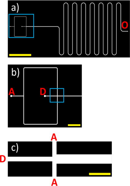
Figure 5.

(a) CAD image of the entire microfluidic mixer design. “O” corresponds to the outlet for the mixed DMF/water streams. A region of interest (depicted in b) is denoted with a blue box. The yellow scale bar corresponds to 1 cm. (b) Zoomed-in image of the inlets of the chip. “D” corresponds to the inlet stream for DMF with dissolved polymer, and “A” corresponds to the inlet stream for the aqueous media. A region of interest (termed flow focusing region; depicted in c) is denoted with a blue box. Yellow scale bar corresponds to 2 mm. (c) Zoomed-in image of the flow focusing region. The yellow scale bar corresponds to 0.5 mm.
