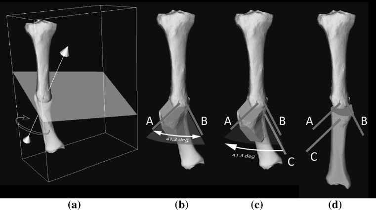
Fig. 3.
Simulation of surgical treatment. a Affected bone and cutting plane showing perpendicular axis of rotation used to bring the distal bone segment in correct anatomical alignment. b Affected bone with cutting guide. The K-wires, labeled A, B are inserted in the proximal bone segment and are used to set the angle of rotation. c K-wire C in the distal bone is parallel to K-wire B before osteotomy, and d rotated until parallel to K-wire A after osteotomy, to achieve rotational alignment

