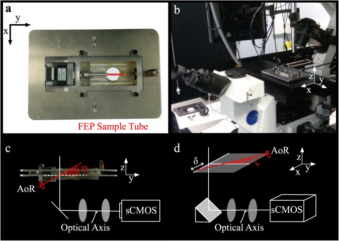
Fig 1.
(a) Photograph of the OPT plate detailing the stepper motor, water-tight chamber and position of the sample tube (shown in red). (b) Photograph of an inverted microscope adapted for OPT, with the plate inserted in the microscope stage aperture. (c) The custom chamber is suspended from an upper plate, with the lower plate seated in microscope stage. For alignment purposes, the axis of rotation (red line) is adjusted until it is orthogonal to the optical axis, setting the tilt angle φ = 0°. (d) In addition the axis of rotation should be approximately centred on the camera sensor and rotated to align with the sensor pixels, setting the shift δ ≈ 0 and rotation angle ζ ≈ 0°.

