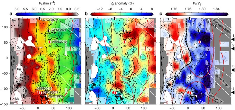
Figure 5. Properties of the plate interface.
Sections of the tomography model along the interpreted slab top surface showing (a) VP, (b) VP anomaly and (c) VP/VS ratio. Areas with sparse ray coverage are covered in grey. Areas with potential strong smearing are faded. The red dashed lines mark the interpreted location of the backstop41. The black dashed lines mark iso-depth contours of the slab (at 50, 100 and 150 km) and the contact of the plate interface with the overriding plate Moho. The thick black dashed line in c marks the transition from high to low VP/VS. The black dashed/dotted lines mark the projection of the major fracture zones on the plate interface. The white dashed lines mark the Tiburon and Barracuda ridges. The red ellipses mark the estimated rupture areas of the 1843 and 1839 earthquakes15. The islands (white) are overlain for reference. Earthquake hypocenters are marked by black dots (all relocated events with epicenter within the slab). Black and white focal mechanisms are shown for relocated flat thrust events. Red focal mechanisms correspond to non-relocated events from the CMT catalogue. The locations of the profiles shown in Fig. 4 are marked by black triangles on the right. Ma, Martinique; Do, Dominica; Gu, Guadeloupe; Mo, Montserrat.

