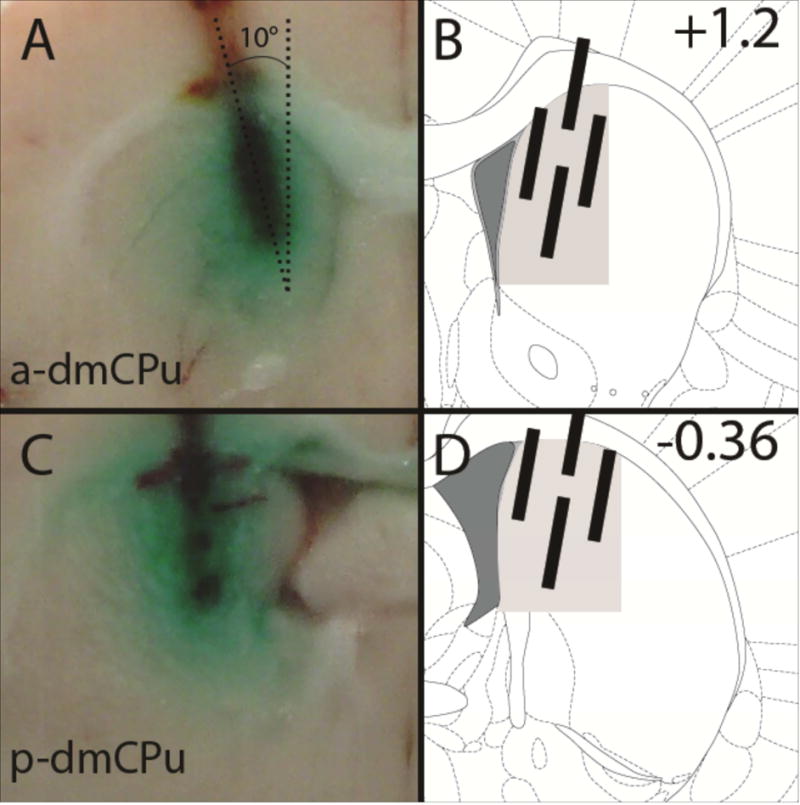
Figure 3.

Photomicrographs of vehicle/dye dispersion in the (A) a-dmCPu or (C) p-dmCPu, 5 min following infusion. Dashed lines indicate 10° angle of cannulae placement for a- and p-dmCPu. (B and D) Graphical representation of targeted areas (shaded in gray) and the acceptable deviations of injector placement on the medial-lateral and ventral-dorsal axis. Numbers on the right panels indicate targeted Bregma position.
