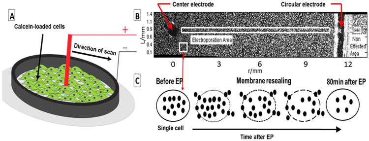
Schematic 2.

(A) A schematic of the electrode-cell monolayer setup in this study. The central electrode (+) and circular electrode (−) position on the cell monolayer loaded with Calcein in a 35 mm dish (B) A radial slice of the disk and the attached cells before start of experiment (C) Illustration of the effect of electroporation on the cell from electroporated area marked by white rectangular in (B). The black dots represent the fluorescent molecules.
