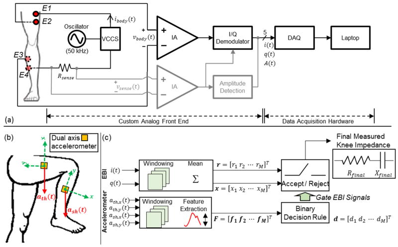
Fig. 1.
(a) A block diagram of the bioimpedance measurement system. E1–E4 represents the electrodes that interface to the body, where E1 and E4 are current electrodes, and E2 and E3 are voltage electrodes. The voltage signal across the resistor, Rsense, (vsense(t)) is used to sense the injected current. The amplitude of this signal, A(t), is detected and used to monitor the amplitude of the current (ibody(t)) passing through the knee joint. The voltage signal vbody(t) is inphase/quadrature (I/Q) demodulated to acquire the signals i(t) and q(t) which relate to the resistance and reactance of the measured segment. VCCS: voltage controlled current source, DAQ: data acquisition system, IA: instrumentation amplifier. (b) Dual axis accelerometers were place on the thigh and the shank to gate the EBI signals. The acceleration signals acquired from the thigh are ath(t)=[ath,x(t) ath,y(t)]T and those acquired from the shank are ash(t)=[ash,x(t) ash,y(t)]T. (c) Algorithm for identifying the time intervals when the user is in the optimal position to acquire measurements (sitting, legs extended and supported). The acceptable time intervals are identified by extracting features from the dual axis accelerometer signals (ath,x(t), ath,y(t), ash,x(t), ash,y(t)) and using these features to make a decision. The binary decision rule is trained once before-hand. The accepted time intervals are used to obtain the knee resistance (Rfinal) and reactance (Xfinal) using the voltage signals i(t) and q(t).

