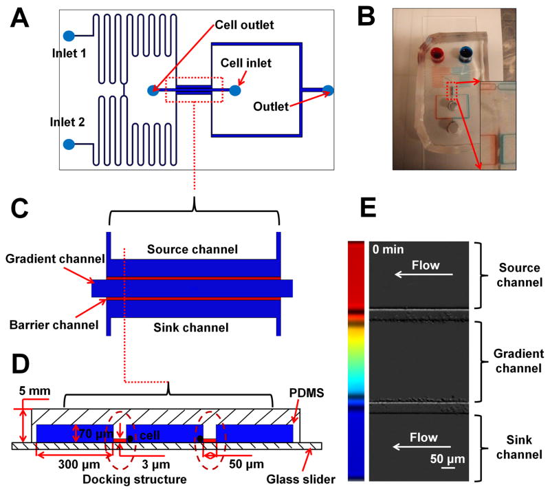
Figure 1. Illustration of the D2-Chip.
(A) Illustration of the design of D2-Chip; (B) A picture of a real D2-Chip. The zoom-in image shows the bridge channel and the region for the parallel gradient channel, source channel and sink channel; (C) Top view of the region for the parallel gradient channel, source channel and sink channel; (D) Side view of the region for the parallel gradient channel, source channel and sink channel; (E) Dual docking of neutrophils at the two sides of the middle channel in the D2-Chip.

