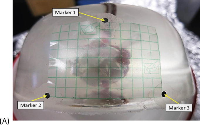
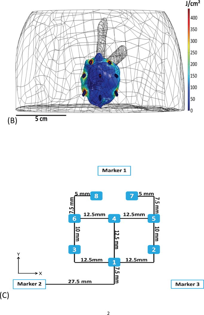
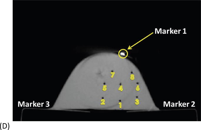
Fig. 1.
Example of basic geometry phantom. (A) The figure depicts the geometry for phantom 2. (B) The figure depicts the intended light dose (J/cm2) for phantom 2 and for a treatment time of 500 seconds. (C) The figure depicts the treatment plan for phantom 2. Note that the origin of the treatment plan starts at Marker 2. (D) The figure depicts the CT scan taken of phantom 2 post catheter insertion.


