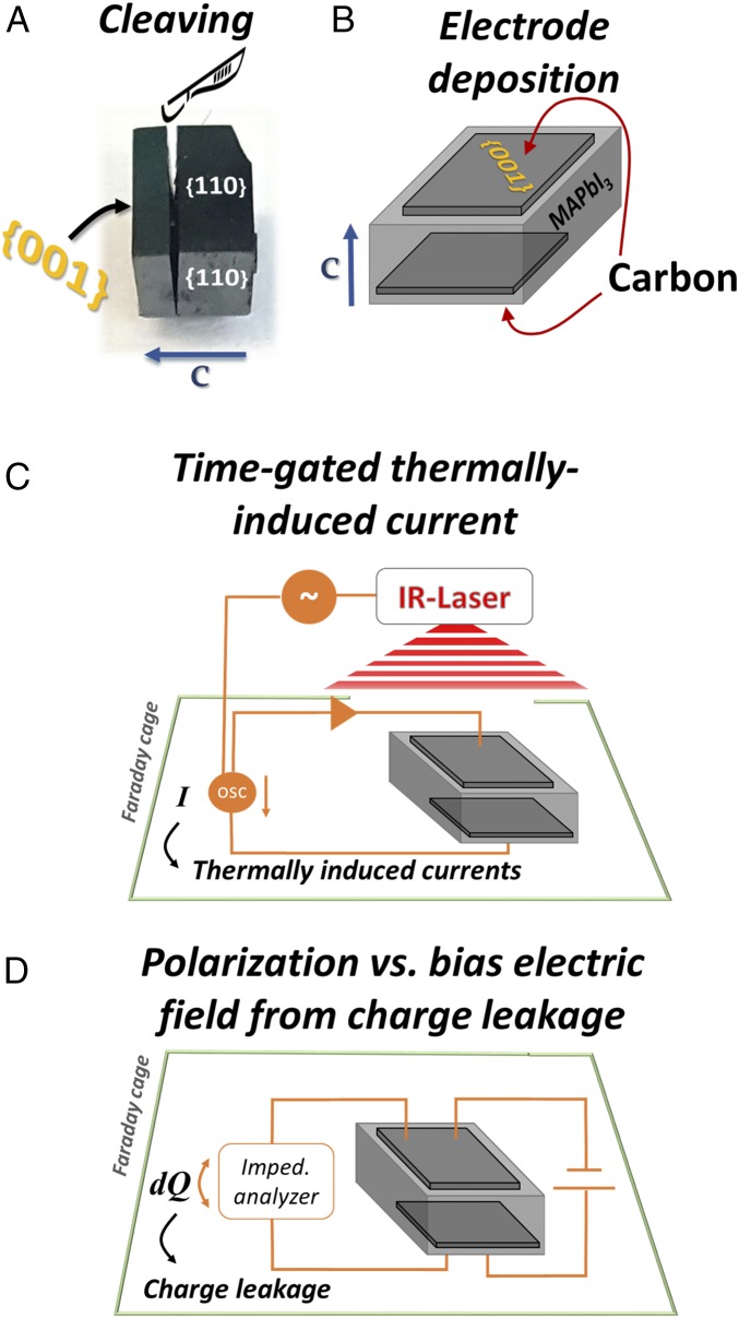
Fig. 7.
Illustrations for sample preparation and dielectric-nature measurements. (A) Photograph of a MAPbI3 crystal (#3), cleaved along its {001} planes after identifying its polar direction. (B) Illustration of the locations where the carbon electrodes were deposited. (C) General scheme of pyroelectricity generation and measurement setup. The circle with the “∼” symbol indicates a function generator. A circle with “OSC” indicates an oscilloscope. A triangle symbol indicates a current-to-voltage amplifier. (D) General scheme of the polarization measurements under external bias.

