Figure 3.

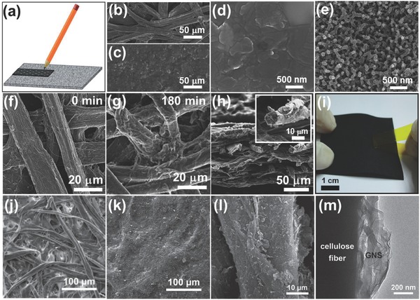
Microstructures of paper‐based electrodes. a) Schematic diagram of drawing conductive electrode on cellulose paper using a graphite pencil. Reproduced with permission.48 Copyright 2013, Royal Society of Chemistry. b–e) Scanning electron microscopy images of (b) blank A4 printing paper, (c, d) graphite paper, (e) G/PANI‐Paper with polyaniline deposition time of 120 min. Reproduced with permission.14 Copyright 2013, Elsevier. f–g) Scanning electron microscopy images for paper coated by polypyrrole with different polymerization times of 0 and 180 minutes, respectively. h) Cross‐section scanning electron microscopy image of the 180 minutes polypyrrole/paper composite. The inset shows an enlarged polypyrrole‐coated cellulose fiber. i) Polypyrrole‐coated paper passes the tape test shows that the strong mechanical property. Reproduced with permission.12 Copyright 2013, Royal Society of Chemistry. j,k) SEM images of the filter paper or GCP surfaces with different GNS loading amounts. j) 0 wt% (pristine filter paper), and k) 7.5 wt%. l) SEM and m) TEM images of a cellulose fiber in a GCP membrane showing GNSs anchored on the fiber surface. Reproduced with permission.59
