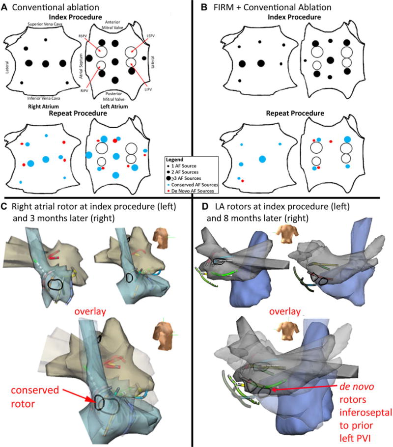
Figure 3.
Electroanatomical shells of conserved and de novo rotor sites, with summary of rotor site distributions for index/repeat procedures. A. Right atrial shells for index/repeat procedures (3 months apart, aligned by basket splines) show rotor at conserved lateral site. B. Left atrial shells for index/repeat procedures (8 months apart) show de novo rotor in posterior left atrium. C. Biatrial schematics show distribution of AF sources at index (top) and repeat (bottom) procedures for conventional ablation, with similar number of sources. D. Sources in the FIRM + conventional ablation group (top: index; bottom: repeat procedures); number of sources is lower at repeat procedure.

