
Figure 2.
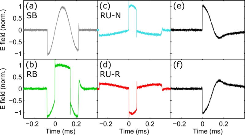
Recorded electric field waveforms of the four rTMS pulses (a)–(d) and the two probing pulses (e)–(f): (a) conventional sinusoidal bidirectional, SB; (b) rectangular bidirectional, RB; (c) rectangular unidirectional with initial anterior–posterior (AP) induced current, RU-N; (d) rectangular unidirectional with initial posterior–anterior (PA) induced current, RU-R; and (e), (f) conventional sinusoidal monophasic pulse with PA and AP initial induced current, respectively. The pulse amplitude was normalized to unity for all pulses. Positive and negative electric field values correspond respectively to PA and AP direction of the current induced in the brain under the center of the figure-of-eight coil.