
Figure 2.
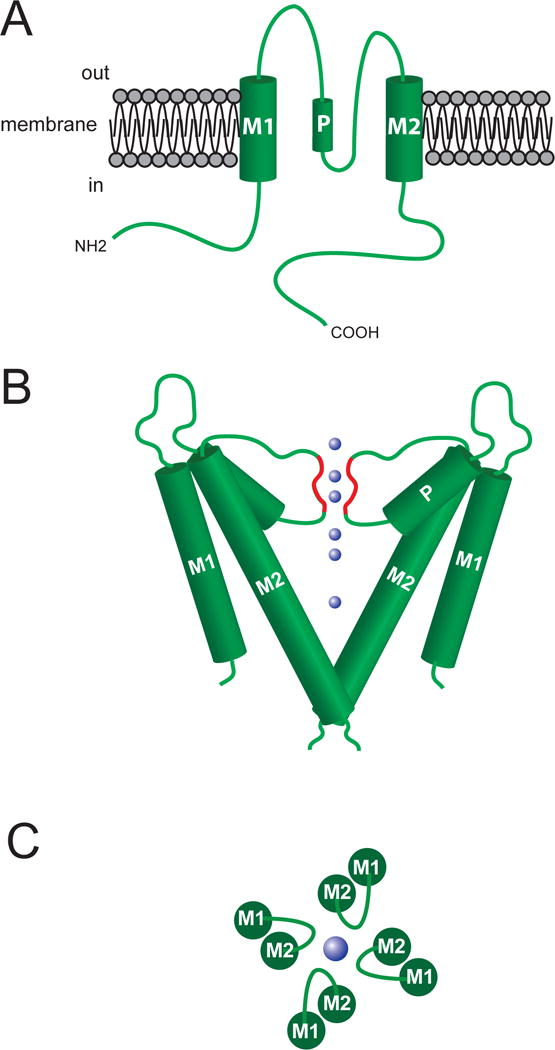
Structure of the ion conducting pore of K+ channels. Top panel (A) shows a schematic representation of a two membrane spanning domain (M1 and M2) K+ channel. Functional channels are formed from a tetramer of these units, with the ion-conducting pore being formed by M2 and the P-loop domain that connects M1 and M2 (P in figure refers to the pore helical domain). Middle panel (B) shows approximate orientation of two sets of the M1, M2 and P-loops forming the channel. The blue spheres represent K+ ions, and the red highlighted regions of the P-loops represent the selectivity filter of the channel’s pore. The bottom panel (C) shows a top view of the channel subunits and the P-loop forming the K+ ion-conducting pore. See text for references.