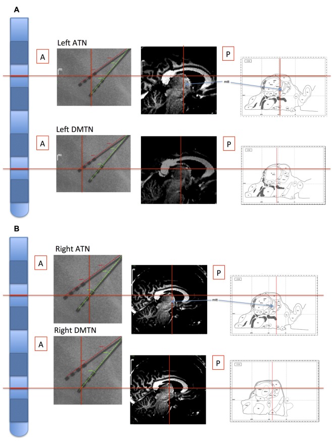
Figure 1.
Illustration of location of recording sites in Patient 4. The electrode probes are represented on the far left, and the levels of the inter-contact points, corresponding with the bipolar channel for each thalamic nucleus, are indicated with horizontal red lines. Left panels: the intra-operative stereotactic X-ray images (lateral view) from which location coordinates were derived. Middle panels: the corresponding locations are superimposed on the pre-operative structural MRI images. By co-registering the images with post-operative CT images, the coordinate positions were determined with reference to atlases (Schaltenbrand and Wahren, 1977; Morel, 2007; Buentjen et al., 2014). Right panels: channel locations with reference to the Morel atlas. (Line drawings from Morel (2007): Copyright © 2007. From “Stereotactic Atlas of the Human Thalamus and Basal Ganglia” by A. Morel. Reproduced by permission of Taylor and Francis Group, LLC, a division of Informa plc). (A) Left channels. (B) Right channels. ATN, anterior thalamic nucleus; DMTN, dorsomedial thalamic nucleus; mtt, mammillothalamic tract.

