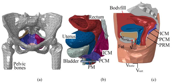
Figure 1.
(a) front view of the pelvic floor muscles and pelvic bone, (b) anterolateral view of the pelvic floor organs and muscles and (c) mid-sagittal view of the complete pelvic model. The velocity boundary conditions are assigned to entire bottom surface and the control point of the rigid bone (represented by the left red spot). The two reference points along the urethra were used to define the urethral excursion angle. Abbreviation used in this figure: ICM–Iliococcygeus muscle, PCM–pubococcygeus muscle, PRM–puborectalis muscle and PM–perineal membrane.

