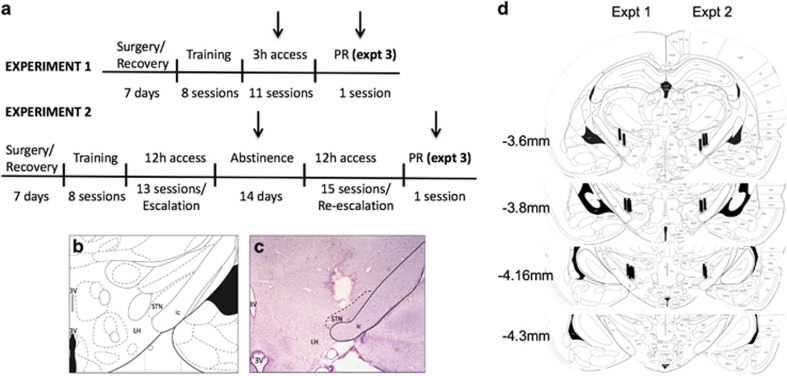
Figure 1.
Experimental design. (a) Experimental timeline for Experiments (Expt) 1–3. Arrows indicate periods of STN HFS. Note that control animals were implanted with stimulating electrodes but were not stimulated to control for the effect of the surgery. (b) Brain atlas. (c) Representative image of the tip of the electrode using Cresyl violet staining. (d) Location of electrodes in Experiment 1 (left) and Experiment 2 (right). ic, internal capsule; LH, lateral hypothalamus; STN, subthalamic nucleus; 3V, third ventricle.

