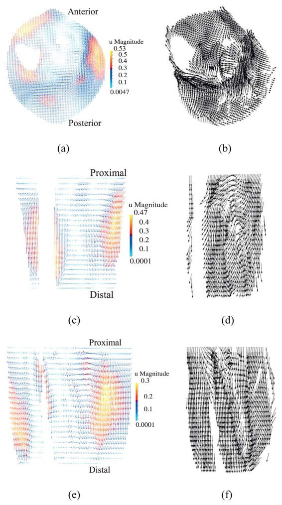
Figure 12.
Displacement vectors (left) and corresponding fiber directions (right) plotted on reference configuration on (a)–(b) transverse plane at z = 5 cm; (c)–(d) coronal plane at y = 10.1 cm; (e)–(f) sagittal plane at x = 10 cm. (units of u magnitude: cm). Note: The fiber directions are plotted only at the muscle points, whereas displacements are shown at all material points.

