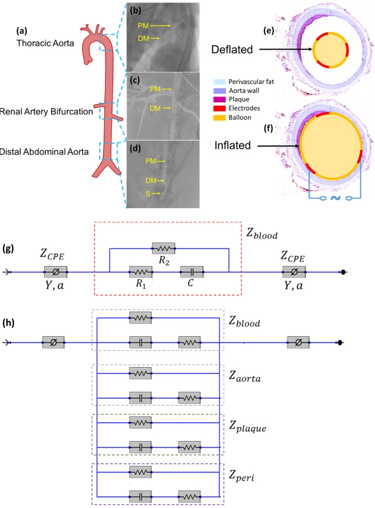
Figure 3.
In vivo sensor deployment and equivalent circuit modeling. The EIS sensor, identified on angiography by the proximal and distal markers, was deployed at 3 levels of the aorta (a), namely the thoracic aorta (b), the abdominal aorta at the level of renal artery bifurcation (c), and the distal abdominal aorta (d). The radiopaque markers made of tantalum (highlighted on the still angiograms by the black circle pointed to by the yellow arrows) permit the identification of the exact position of the device within the aorta. A cross-sectional perspective of the deflated (e) and inflated (f) balloon in the aorta shows specific electrodes to perform the endoluminal EIS measurement. The equivalent circuit includes the blood as primary circuit component upon balloon-deflation (g). The equivalent circuit further includes the aorta, plaque, blood, and perivascular fat all as the circuit components upon balloon-inflation (h). Legend. C: capacitive element. CPE: constant phase element. DM: distal sensor marker. Y: nominal capacitance value, 0<a<1. PM: proximal sensor marker. R: resistive element. S: sheath.

