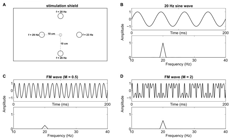
Figure 1.
Stimulation device and signal overview. (A) Custom stimulation shield with a small central fixation light-emitting diode (LED) and four stimulation LEDs at 10 cm (5.72° visual angle at 1 m distance) radial distance. One specific Steady-state visual evoked potential (SSVEP) frequency was assigned to each stimulation LED throughout the experiment. (B) A 20 Hz sine wave which was used to drive one LED, and the respective frequency spectrum. (C) A frequency modulated (FM) signal (100 Hz carrier, 80 Hz modulation frequency and a modulation index of 0.5) and its frequency spectrum. (D) A signal with the same parameters as in (C) except that the modulation index is increased to 2. This leads to an increased peak in the spectra at 20 Hz.

