
Figure 1.
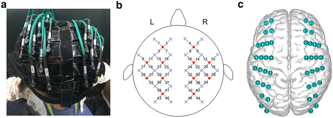
Schematic of fNIRS channel localization. (a) Photograph of fNIRS measurement of a participant. (b) The schematic of the imaging pad (12 sources, red circle and 24 detectors, blue cross). The sources and detectors were symmetrically placed on the left and right hemispheres and constituted 46 measurement channels, which allowed for the most brain regions (i.e., frontal, temporal, parietal, and occipital lobes) on two half-hemispheres to be measured. (c) The anatomical position of each measurement channel.