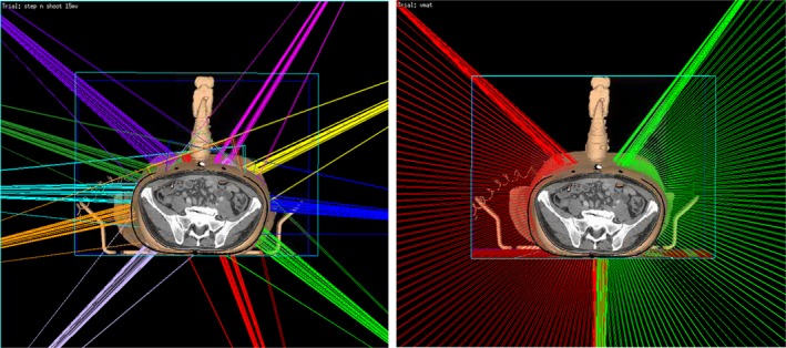
Figure 8.

The 3D rendering of beam orientations for virtual simulation IMRT plan (left) and VMAT plan (right) of an example patient from this study in our planning system Pinnacle. The step‐and‐shoot IMRT plan consists of 10 beams, each beam has 5–10 segments. The VMAT plan is composed of two arcs; each arc has about 70 control points. Gantry angle interval between two consecutive control points is 2°. In both IMRT and VMAT plans, the beam is restricted as least 30° away from the probe.
