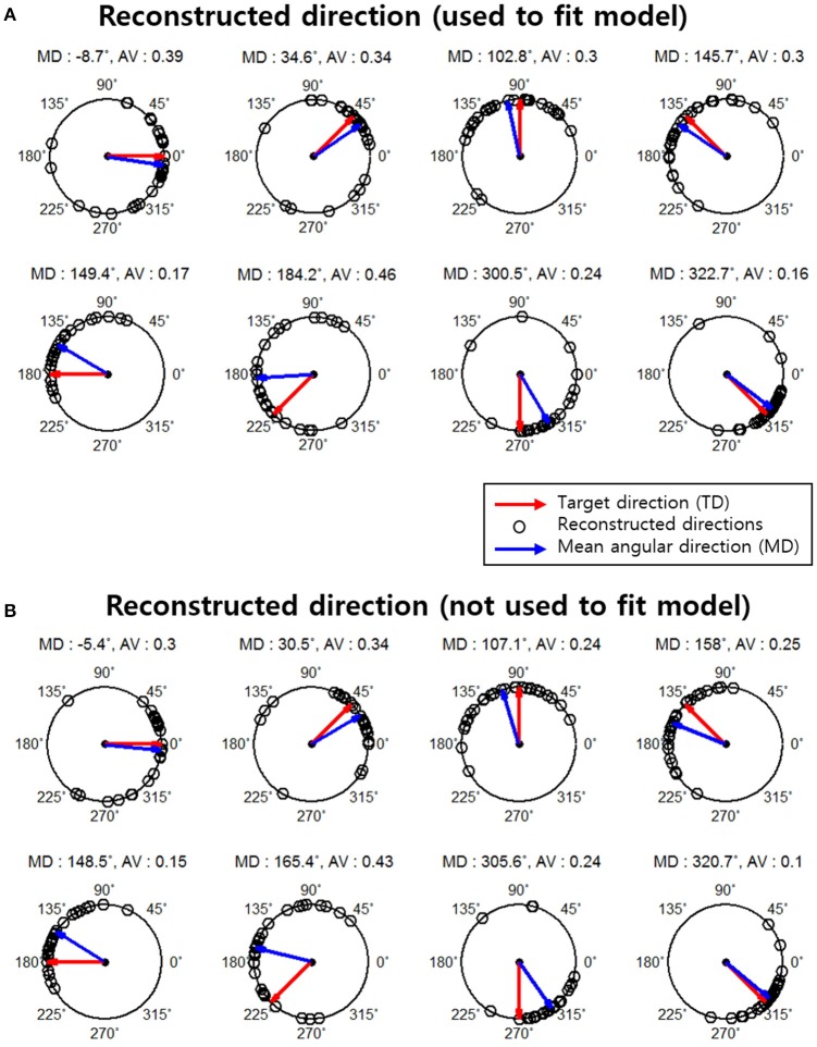
Figure 4.
Reconstruction results for subject 1. The red arrows indicate the actual movement directions (target directions). Black points indicate the reconstructed directions on a single-trial basis (total 30 reconstructed directions in each movement direction. The blue arrows represent the mean angular direction for all reconstructed directions in each target direction. The mean angular direction was obtained by means of vector addition. The angular variance (AV) was defined as AV = 1− ∥ r ∥ and the interval of the AV was [0, 1]. ∥ r ∥Indicates the length of the mean angular direction. (A) Results of the reconstructed directions that were used to fit the encoding model. (B) Results of reconstructed direction that were not used to fit the encoding model.

