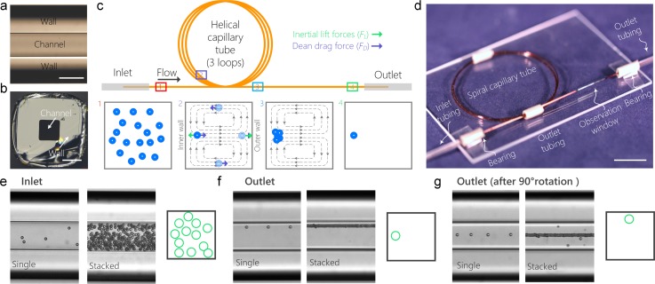
FIG. 1.
Device principle, fabrication and operation. (a) Bright-field top-view microscopic image of the capillary tube. The scale bar is 100 μm. (b) Bright-field microscopic image of the cross-section of the capillary tube. The scale bar is 100 μm. (c) Schematics of the principle of single-position focusing of cells in a 3-loop helical capillary tube. The inset schematics 1–4 illustrate particle distribution in the channel cross-section at the corresponding downstream positions. The grey dashed lines in inset schematics 2 and 3 represent the Dean vortices. The green and purple arrows represent the net lift force FL and Dean drag force FD, respectively. (d) A photograph of the device mounted on a glass substrate. (e) Single and stacked bright-field microscopic images and cross-sectional schematic showing that particles are distributed randomly at the inlet of the device. (f) Single and stacked bright-field microscopic images and cross-sectional schematic showing that particles are tightly focused into a single position after traveling through the device. (g) Rotation of the device for 90° enables the observation of particle focusing from side view, which further confirms the tight single-position focusing. In all the three panels, the images at the left and right hand sides are single and stacked images (n = 100), respectively.

