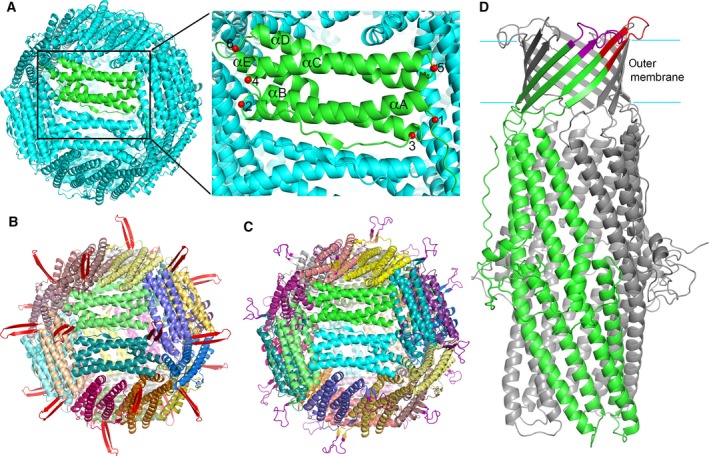
Figure 1.

Computational design of the Hpf‐loop nanoparticles. (A) Hpf structure and potential insertion sites for antigenic N. gonorrhoeae peptides on the structure of ferritin. The Hpf structure (Pdb code 3BVF) is shown in cartoon representation. One subunit is colored in green, while the rest in cyan. The potential insertion sites for N. gonorrhoeae peptides are marked on the green subunit with red spheres and numbered from 1 to 6. Helices αA to αE are labeled. (B) Computational model of an Hpf‐E1 nanoparticle. The MtrE loop 1 (colored red) is inserted at site 2, replacing His34. A two‐stranded β‐sheet projects the loop outward from the surface. (C) Computational model of Hpf‐E2. The MtrE loop 2 (colored purple) is inserted at site 1, the N terminus of Hpf. (D) Cartoon representation of the MtrE structure (Pdb code 4mt0) showing the peptides loop 1 (colored red) and loop 2 (colored purple) that were selected to build Hpf‐E1 and Hpf‐E2, respectively. One subunit of MtrE is colored in green with the surface loops marked, and the other two subunits in gray.
