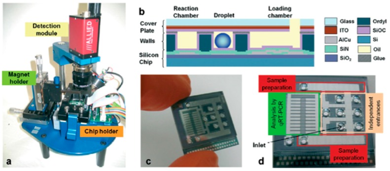
Figure 4.
DMF device assembly: (a) Additional instrumentation for the DMF chip control; (b) Chip cross section, evidencing all the constituting layers; (c,d) Photographs of the actual DMF chip, showing the most relevant chip regions. Adapted from original in reference [24].

