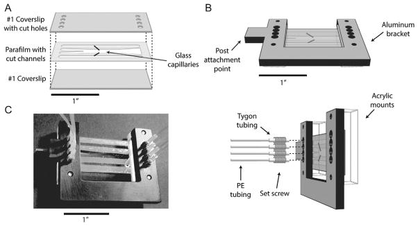
Fig. 8.
Laminar flow cell layout. (A) Chambers are assembled from a piece of parafilm melted between two #1 coverslips. The top coverslip has inlet holes cut into it. The parafilm has patterned into it two outer channels for flowing in beads, and a central channel consisting of two laminar flow streams for assembling complexes in situ. Two glass capillaries connect the top and bottom channels to the central channel and are used to dispense beads. (B) An assembled flow chamber is mounted on a custom aluminum bracket into which tubing mates with the inlet holes. The tubing assembly consists of PE tubing inserted into short lengths of Tygon tubing threaded through set screws screwed into the bracket. (C) Photograph of a flow chamber.

