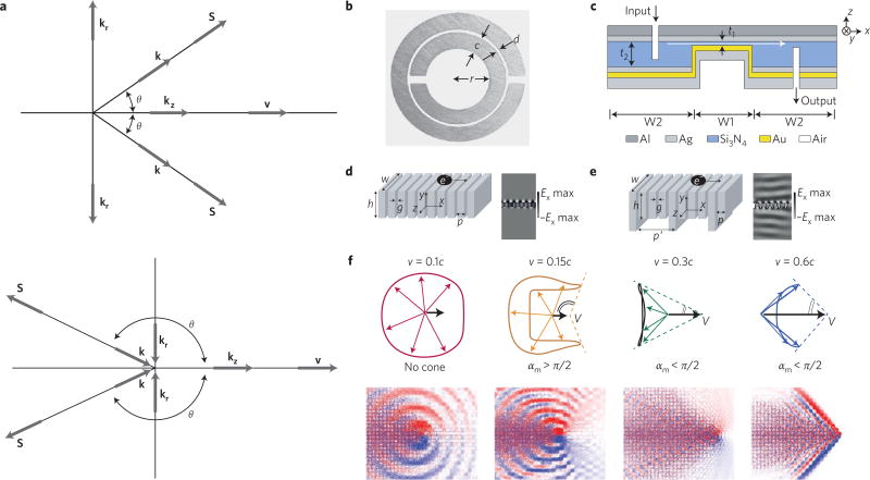
Figure 7. The Cerenkov mechanism can be modified in unique ways through interaction with metamaterials and photonic crystals.
a, The Vavilov-Cherenkov effect in a positive n (top) and a left-handed n (bottom) substance, where v is the particle velocity, k is the wavevector, S is the Poynting vector and θ is the cone angle formed. Traditional positive n material creates a forward facing Cherenkov cone with angle θ, while negative n material produces an obtuse cone, where the cone angles in the opposite direction to the particle velocity. b–e, Metamaterial examples utilizing CL in practice or conceived in theory. b, Copper split ring resonator with dimensions: ring width c = 0.8 mm, ring spacing d = 0.2 mm and inner radius r =1.5 mm. c, Diagram of Au–Si3N4–Ag waveguide ~500 nm in height for in-plane negative refraction, where t1, is the variable dielectric core thickness with edge angle θ, representing section W1 embedded in the waveguide of fixed core thickness t2 = 500 nm, representing section W2. d,e, Metamaterial structure 1 (d) and structure 2 (e) with periodic air slits in the metal denoted, g and p, where structure 2 introduces an additional periodicity with dimensions h′ and p′. Addition of periodicity amplifies the CL intensity produced in the far field (CL intensity profile right of structure design, denoted Ex) as represented by the energy density ripples at discrete angular frequencies ω. f, Top: finite-difference time-domain simulation results for CL in a photonic crystal. Each column represents the results for the value of velocity (v) shown on the top, where c is the speed of light in a vacuum. Overall radiation cone shapes (dashed lines) deduced from the group velocity contours where αm is the angle of the overall radiation cone. Bottom: distribution of the radiated magnetic field. Blue, white and red represent negative, zero and positive field values, respectively. The colours have been chosen separately for best illustration in each case. Panels reproduced from ref. 63, IOP (a), ref. 65, APS (b), ref. 72, AAAS (c), ref. 81, OSA (d,e) and ref. 87, AAAS (f).

