
Fig. 18.
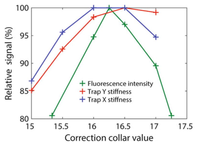
Adjustment of front objective (FO) correction collar (collar shown in Fig. 20a). Relative fluorescence intensity and trap stiffnesses in the x and y directions from a trapped fluorescent bead as the correction collar is adjusted. The fluorescence intensity and trap stiffness do not reach a maximum at the same collar position likely due to chromatic aberrations in the objectives