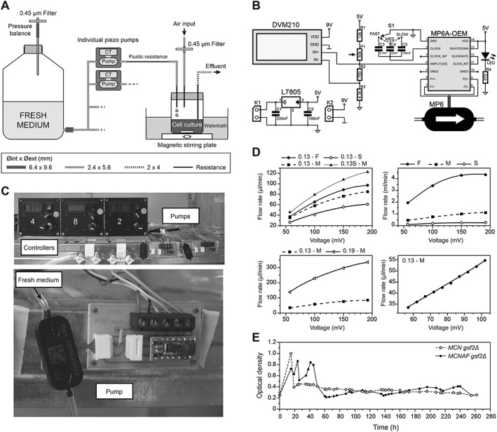
Figure 4.

Development of a system for independent control of individual cultures. (A) Schematics of the new system integrating piezo pumps and their controllers (CT). A fluidic resistance downstream of each pump was required to reduce the flow rate to the appropriate range. The diameter of the different tubes is indicated. (B) Electronic scheme of the pump control system. MP6: piezo pump. See ‘Materials and methods’ for details of the system. (C) Representative images of the pump system. The top panel shows three control panels and two piezo pumps with their controllers. The bottom panel is a detailed view of a piezo pump and its electronic controller. (D) Changes in fluidic resistance allow for a broad range of flow rates. Top left: a 0.13 mm inner diameter resistance of 37 cm was used at fast (F), medium (M) and slow (S) frequencies for the pump. Shortening this resistance to 23 cm (0.13S–M) has a strong effect on flow rate. Top right: in the absence of fluidic resistance, very high flow rates can be obtained. Bottom left: changing the inner diameter of the resistance (0.13 vs. 0.19 mm here at medium frequency) has a strong effect on the flow rate. Bottom right: this system allows for fine modulation of the flow rate – shorter steps in voltage were used with a 0.13 mm fluidic resistance of 37 cm at a medium frequency, displaying a linear relationship between the imposed voltage and the flow rate. (E) Proof‐of‐concept experiment using the pump setup. 20 mL aliquots of MCN gsf2Δ and MCNAF gsf2Δ cells were grown in the new ministat system over 10 days (EMM6S + 3% galactose at 28°C), individually modulating the dilution rate of each culture throughout the experiment by only using the piezo pump parameters. After the usual first 48 h required for stabilization of the cultures, both strains were maintained at constant densities in exponential growth, despite their significantly different generation times (see main text).
