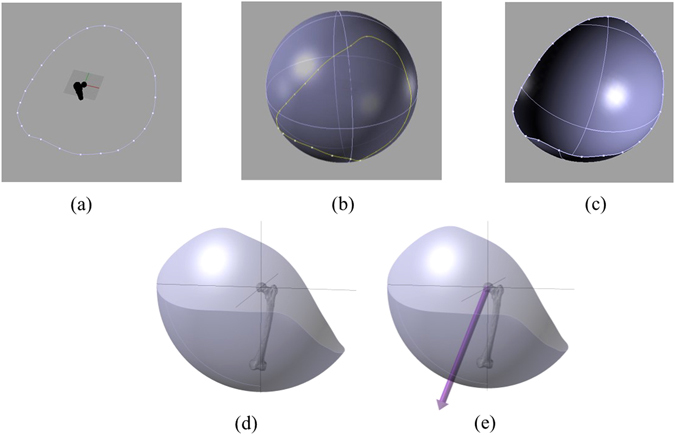
Figure 3.

Schematic representation of the modelling procedure to construct subject-specific post-operative ROM area. (a) A set of collision points represents ROM boundary, (b) A sphere containing the ROM boundary. Centre of the sphere is the centre of rotation of ROM simulation and radius is the distance between the centres of rotation to the knee centre. (c) ROM area. (d) ROM area in another view. (e) Directional axis for prosthetic ROM area.
