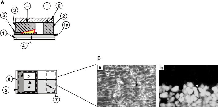
Figure 1.

Electrode and slide assembly for the study of intercellular, junctional communication: standard slide. (A) Top panel: side view. A coating of ITO (1a) (shown greatly enlarged for clarity) on the upper surface of the glass slide (1) makes a conductive path from the positive contact bar (2), through the cells (4) and the electroporation solution to the bottom surface of the negative electrode (3). + and − denote connections to the positive and negative poles of the pulse source, respectively. (5), insulating Teflon frame, (6), electrode holder. Note that the negative electrode is inclined to compensate for the resistance of the coating (Raptis et al., 2006). Lower panel: top view. The outline of the positive (7) and negative (8) electrodes and their relative position on the slide in relation to the frame (5) and the window where the cells are grown are indicated. The lightly shaded area (a) represents the conductive coating. (b), area where the conductive coating has been removed. Arrowhead points to the transition line between conductive and non‐conductive areas. (B) Examination of gap junctional communication using the above apparatus. Human lung carcinoma A549 cells were plated in the window (a,b) as shown in (A) and electroporated in the presence of 5 mg/ml Lucifer yellow. After washing the unincorporated dye, cells from the same field were photographed under fluorescence (right panel) or phase contrast (left panel) illumination. Arrows point to the transition line between conductive and non‐conductive areas. Note the absence of fluorescence in cells growing on the nonconductive part of the slide (Tomai et al., 1999).
