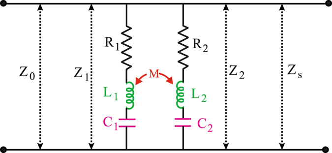
Figure 6.

Schematic of TL-RLC circuit model. The circuit components R 1, L 1, C 1 represent resistance, inductance and capacitance related to lower order resonance and R 2, L 2, C 2 represent the same related to higher order resonance. M is the mutual inductance, responsible for coupling between resonances. Z 1 and Z 2 are impedances due to two circuits, respectively whereas Z 0 and Z S represent impedances of free space and silicon substrate, respectively.
