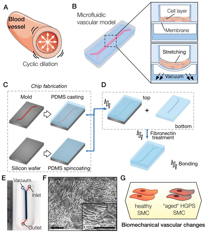
Figure 1. Recapitulation of blood vessel dynamics on chip.
(A) Blood vessels experience cyclic strain due to the pulsatile nature of blood flow. (B) Biomimetic microfluidic vascular model containing two overlapping channels. A cross-sectional view of the microfluidic device shows the cell layer cultured on top of the PDMS membrane and a view during vacuum stimulation shows the downward membrane deformation. (C) The first step of the chip fabrication containing the casting of PDMS (10:1 ratio) on an acetal resin mold and the spincoating of PDMS (20:1 ratio) to generate a thin membrane on top of a silicon wafer. (D) The top slab and membrane portions of the PDMS device are bonded using oxygen plasma and then peeled off the silicon wafer. The top part is then bonded to the bottom PDMS slab molded previously, and treated with fibronectin solution to allow cell culture. (E) Photograph of the microfluidic channel showing the media inlet, outlet and the vacuum port. (F) Micrographs of SMCs cultured in the microfluidic chip (scale bar represents 250μm). (G) Proposed methodology to unveil strain-related vascular changes in iPS-derived SMCs from healthy and HGPS donors.

