
FIG. 2.
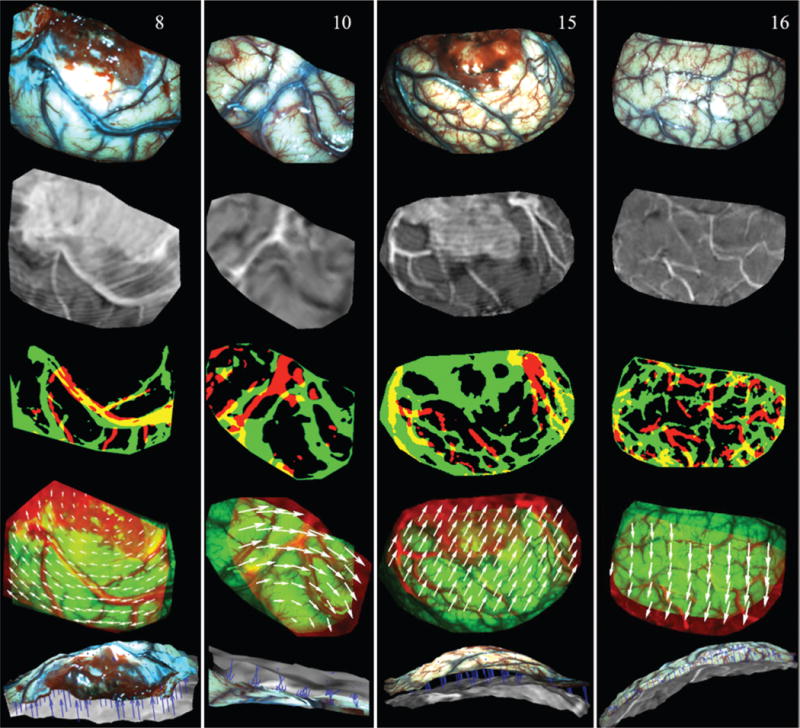
Illustration of surface registration between iSV and pMR for Cases 8, 10, 15, and 16 (columns left to right). The first and second rows show the iSV texture maps and pMR-encoded images, respectively. Thresholded binary iSV (green) and pMR (red) images are overlaid in the third row, and misalignment indicates lateral shift of the cortical surface. The fourth row presents an overlay of iSV (green) and pMR (red) images after registration, in which the 2D displacements appear as white vectors. The fifth row shows an overlay of the iSV (colored) and pMR (grayscale) brain surfaces where the extracted 3D displacements appear as blue vectors (pointing from pMR to iSV). Figure is available in color online only.