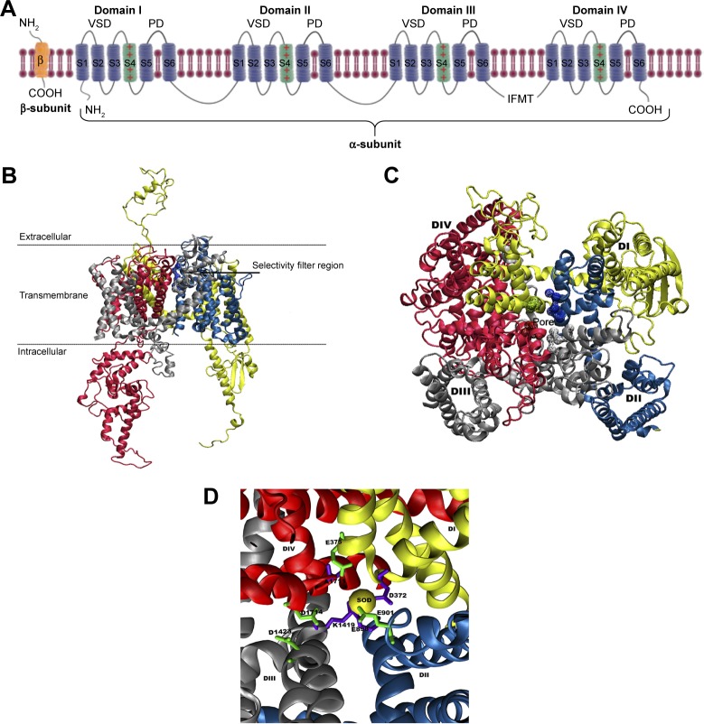
Figure 1.
(A) A schematic representation of the α- and β-subunits of a complete VGSC model. The figure depicts all the four domains (I–IV), with each domain including a VSD and a PD. The positively charged S4 helical segments of the VSDs, which connect with the respective PD, are shown as green helices and the location of inactivation gate is also marked. The 3D structure of the homology model of hNav1.5 ion channel is shown as (B) side-view and (C) top-view representations. The locations of the SFs residues are given in (D) and colored green (outer SF, EEDD) and violet (inner SF, DEKA). A trapped sodium ion is shown as a yellow van derWaals sphere. The four domains, DI, DII, DIII, and DIV, are shown in yellow, blue, silver, and red, respectively.
Abbreviations: PD, pore domain; SF, selectivity filter; VSD, voltage-sensing domain.

