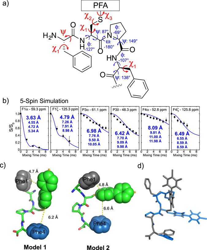
Figure 6.

Two structural models for PFA-tagged π-clamp show similar backbone structures but distinct Phe1-PFA interaction. (a) The average predicted backbone torsion angles (shown in blue) and the torsion angles varied for fitting (shown in red). (b) Representative model-dependent, best-fit 5-spin SIMPSON simulations of the experimental REDOR curves for the resolved 13C sites. For each simulation of torsion angle combinations, the four nearest 19F atoms to a 13C site were included in the simulation. (c) Structural model of the PFA-tagged π-clamp motif based on the predicted backbone torsion angles and REDOR distance restraints. Model 1 (left) uses Phe1 Cα and Cβ for fitting, giving torsion angles of Phe1 ψ = 90° and χ1 = −60°, Cys2 χ1 = 60°, χ2 = −60°, and χ3 = −30°, and Phe4 χ1 = −90°. Model 2 (right) uses Phe1 Cα’ and Cβ’ for fitting, giving torsion angles of Phe1 ψ = −60° and χ1 = 150°, Cys2 χ1 = −120°, χ2 = 180°, and χ3 = 180°, and Phe4 χ1 = −120°. The shortest carbon-to-carbon distance between Phe side chains and PFA were shown. (d) Superimposition of the two models around Pro3.
