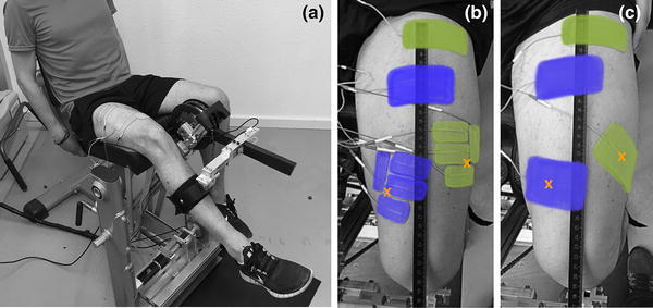
Fig. 1.

a The knee dynamometer measuring the power output of the right leg during stimulation with the SES setup. The leg brace, the lever arm with the load cell and the chain drive system are visible. b SDSS setup with the four small electrodes replacing the active electrodes. Electrodes were placed as close as possible to the located motor points. c SES setup with two pairs of electrodes. Active electrodes were placed on the motor points of m. vastus medialis and m. vastus lateralis. Motor points are highlighted with an orange cross (colour figure online)
