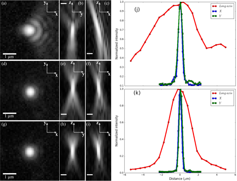
Fig. 6.
The PSF of our microscope without and with aberration corrections from the deformable mirror, all displayed with log scaling. All scale bars are 1 μm. In (a)–(c), only the cylindrical lens placed in the imaging path corrects some of the aberrations. The deformable mirror is flat. In (d)–(f), a pattern is placed on the deformable mirror found through iteratively finding the pupil function and adjusting the deformable mirror. In (g)–(i), a sheet of excitation light coming from an orthogonally placed objective is used rather than using wide-field illumination as in the previous cases. (a), (d), and (g) display slices of the PSF in the x-y plane. (b), (e), and (h) display slices in the z-y plane. (c), (f), and (i) display slices in the z-x plane. (j), (k): Cross sections of the PSFs in x, y, and z directions before and after the aberration correction.

