Fig. 4.

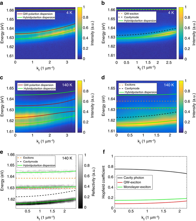
Hybrid polariton dispersion relation in a hybrid Tamm structure containing a monolayer of MoSe2. a Angle-resolved photoluminescence measurement at the Tamm device with the monolayer at 4 K. The red line represents the calculated polariton dispersion and the green line shows the hybrid polariton dispersion for a slightly wider cavity (~1 nm corresponding to 3 meV energy shift) at the flake position. b Same dispersion measurement as a but with strong spatial filtering at the flake position. The energy of the QW exciton is represented by the dashed yellow line and the cavity mode at the flake position by the dashed black line. The MoSe2 exciton energy of 1.666 eV is not shown on this chart. c PL dispersion measured at 140 K with the same colour coding as before. d Same measurement as c but with strong spatial filtering at the flake position. The energy of the MoSe2 exciton is shown by the orange dashed line. e Angle-resolved reflectivity measurement with strong spatial filtering at the flake position. f Calculated Hopfield coefficients for the lower hybrid polariton branch
