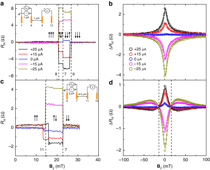
Fig. 2.
Non-local spin-valve and Hanle measurements at different DC bias across the injector. a, c: Non-local differential spin-valve signal R nl (=v/i) as a function of the magnetic field B y applied along the easy axes of the Co electrodes, for a short (L = 1 μm) a, and a long (L = 6.5 μm) c spin transport channel. An offset at zero field is subtracted from each curve for a clear representation of the data. The vertical dashed lines correspond to the switching of the electrodes at their respective coercive fields. The switch of the outer detector 13 is not detectable as it is located far (>2λ s) from the nearest injector. The legend shows the applied injection DC current bias I in values. The up (↑) and down (↓) arrows represent the relative orientation of the electrode magnetizations. The three arrows in a correspond to the contacts 7, 8, and 9, and the two arrows in c correspond to the contacts 7 and 11, from left to right. The insets in a and c show the measurements schematics, injection AC current (i) and the DC current bias (I in), the respective contacts used for the spin current injection, and non-local differential voltage (v) detection. The differential spin signal in a due to spin injection through 8 is , and in c due to spin injection through 7 is . b, d Non-local (differential) Hanle signal ΔR nl(B z) as a function of the magnetic field B z. b, d shows ΔR nl measured for the short(long) channel, corresponding to the spin injector contact 8(7) and measured with the detector contact 9(11). The measured data are represented in circles and the solid lines represent the fits to the data. Hanle signals in b at different injection bias values . The two vertical dashed lines in d correspond to the fields where the Hanle signals cross zero

