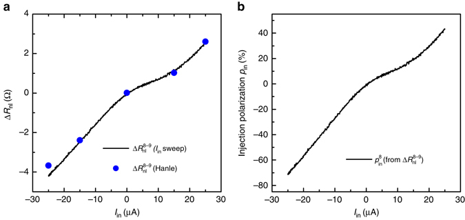
Fig. 3.

Bias enhanced non-local differential spin signal and large differential spin-injection polarization at room temperature. a Non-local spin signal (I in) corresponding to the spin current injected through contact 8 and detected via contact 9, as a function of the DC current bias (I in) applied across the injector. The solid line represents the spin signal (I in) for a continuous sweeping of the I in bias, while the dots are extracted from the Hanle signals (B z) at B z = 0, measured at different bias (from Fig. 2b). b Differential spin-injection polarization of the injector contact 8, as a function of I in, calculated from the (I in) (Eq. (3)) data plotted in a
