Fig. 5.
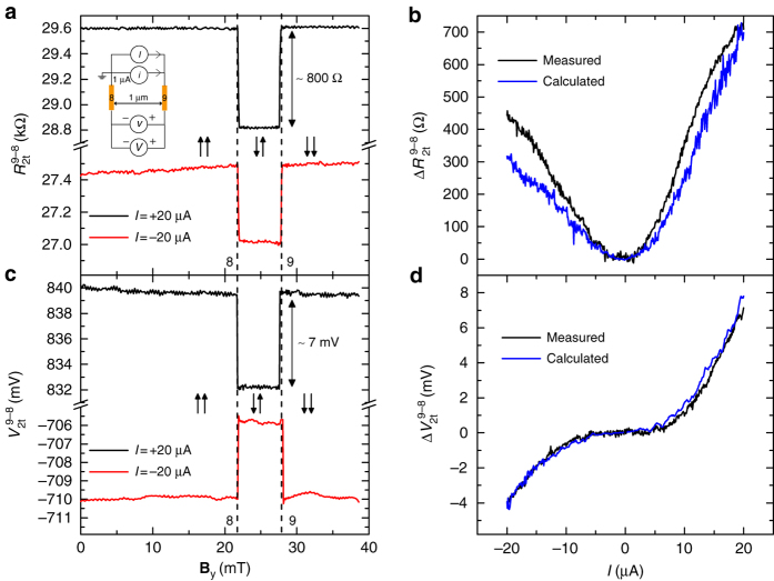
Large inverted two-terminal spin-valve effect at room temperature. a Two-terminal differential spin-valve signal R 2t(=v/i) and c two-terminal DC spin-valve signal V 2t, as a function of B y at two different DC current bias values. The inset in a illustrates the two-terminal spin-valve measurement configuration. The arrows ↑↑ (↓↑) represent the parallel (anti-parallel) orientation of the magnetization of contacts 8 and 9, respectively, from left to right. The vertical dashed lines represent the coercive fields of contacts 8 and 9. b Two-terminal differential spin signal ΔR 2t(I), and d two-terminal DC spin signal ΔV 2t(I), as a function of the DC current bias I. The calculated two-terminal spin signals from the individual spin-injection and detection polarizations of contacts 8 and 9 are also shown in b and d

