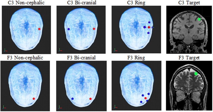
Figure 1.
The top row shows the electrode configurations on the top of the head for non-cephalic, bi-cranial, and ring. The green circle in the coronal MRIs shows an image of the current sampling area (green dot) under the C3 and F3 electrodes where the current calculations were made for each configuration. Red electrodes are positive, and blue electrodes are negative. The top row is the C3 electrode locations, and the bottom is the F3 locations.

