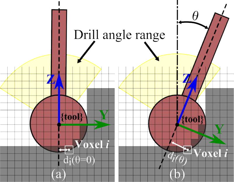
Fig. 3.
Cross-sectional illustration of the range of permissible angles at a given point along the path. Optimal shaft angle (θ) is determined based on the intensity and location of each voxel with respect to the drill shaft (di). Note that di also has a component in the x-direction in the 3D case and all of the voxels being cut are at the surface of the spherical burr. The figure shows how the distance between the shaft axis and the center of a single voxel changes with θ.

