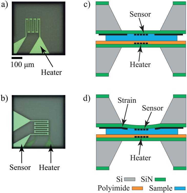
Fig 3. Schematic drawings of device and sample preparation for thermomechanical gelation measurement setup.
(a) and (b) are top view of the setup, and (c) and (d) are the cross-sectional view of the setup. a) Top view of the heater device via optical microscope camera. b) The sandwich configuration of the sensor and heater with sample in between. The transparency of the membrane allows optical alignment of the sensor over the heater device. c) Cross-sectional view of the measurement configuration, where the heater is coated with polyimide film while sensor is plain. d) Membrane deflection due to the stress exerted by volumetric change of sample during the phase transition.

