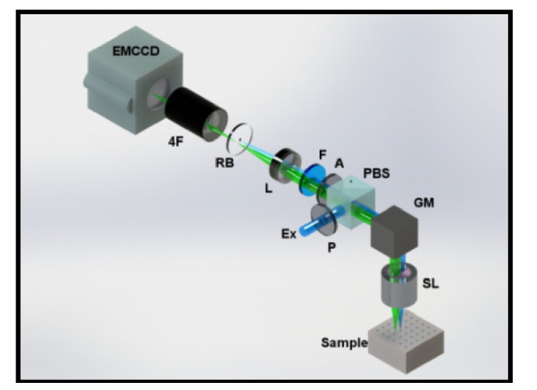
Fig. 1.

Optical schematic diagram of the 2nd Generation MFMT system. The de-scanned excitation (Ex) light and 2D detector array (EMCCD) compose the system backbone. Polarizing beam splitter (PBS) and cross-polarizers (P, A) minimize specular reflection from the sample surface along with the fluorescence filter (F). Scan lens (SL) and a tube lens form a conjugate image plane and 4F relay system forms the final image on the EMCCD. In higher binning configurations, the spatial integration of the photons deteriorates the dynamic range so a reflection block (RB) is introduced into the system. One set of images is completed after completing a raster scan.
