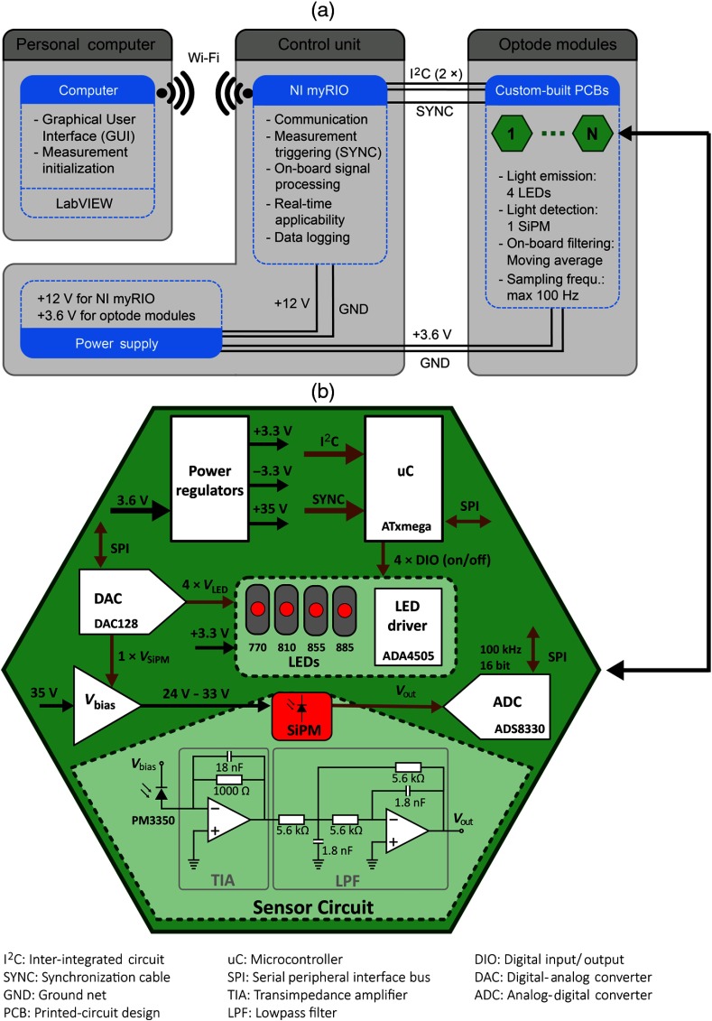
Fig. 2.
Schematic diagram of the fNIRS instrument. (a) The three main components of the instrument, including a computer, a control unit consisting of the NI myRIO, and a battery, as well as optode modules. (b) Diagram showing the electrical components of the custom-built optode modules. Black arrows represent power lines, and brown arrows represent signal lines.

