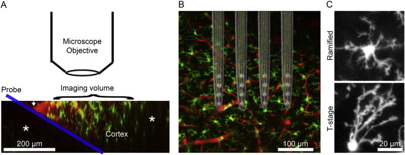
Fig. 1.
Experimental set-up. A) Following craniotomy, the probe (blue) is inserted into the cortex (Microglia in green; blood vessels in red) at a 30° angle. The white arrow indicates where the cortex is pierced. This allows the probe to be inserted without colliding with the microscope objective while maximizing the area of the probe that can be imaged. * denote darker regions due to being underneath either the probe or pial blood vessels. The image shown here is a side-projection of raw data made through a 3D reconstruction. B) Raw data were images of cortex from a “bird’s-eye view”. Here, a bright-field image of the neural probes is superimposed over unimplanted cortex to demonstrate probe configuration and relative of cortex and implants. The implanted probes are 4-shank, silicon Michigan-style electrodes with Ir electrode sites. C) Microglia are classified as ramified if processes extend equally in all directions or as “activated” transition stage (T-stage) if processes extend in one direction preferentially. (For interpretation of the references to colour in this figure legend, the reader is referred to the web version of this article.)

